 |
DIY • Do it Yourself • Weekend Projects • BIG Projects • LITTLE Projects | |||||
|
DIY • Do it Yourself • Weekend Projects • BIG Projects • LITTLE Projects | |||||
How Do I Share My How-To?It's really pretty easy, pictures and videos of the steps it takes to complete your project are stored on YouTube and picasaWeb. Once your "final" video is stored on YouTube, your project will show in the listings on the site. All this is controlled by our Creator's Tools. Basically, you start a project by writing up the project idea. Step 1. Sign up for a free Creator's Account to gain access to the Creator's Tools. Step 2. Login Step 3. Push the "Create New Project" button on the Creator's Tools. Make a name (you can change it later) for your project. And describe your plans to use as notes to guide the creation of the steps. Step 4. When you've finished providing all the steps to your project, shooting the videos and saving to google video via the Creator's Tool Panel, you are ready to write the introductory paragraph with an interesting story of how you did it, or how you do it in the case of a professional services presentation. Step 5. Last but not least create and upload the video (to YouTube) which is the video that will be used to summarize the project. If you were building a robot, this final video would show the robot running around, doing fun things that will inspire others to create their version of your project. That's it... Watch the views and ratings for your project pile up along with the sales commissions! Or get a customer because you showed how you remodel a house. |
FAQ About Becoming A CreatorQ. Why would I go to all that work, building something, then put it on a website like C What I Can Do? What's the point? A. Actually, there are a couple of forms for a reward:
|
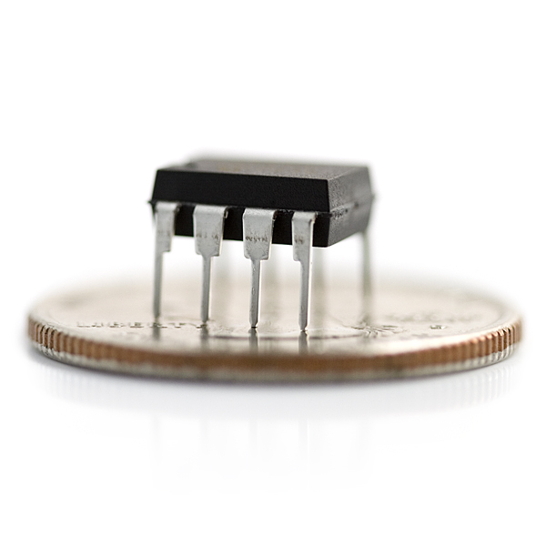
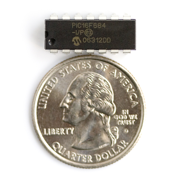
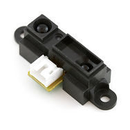
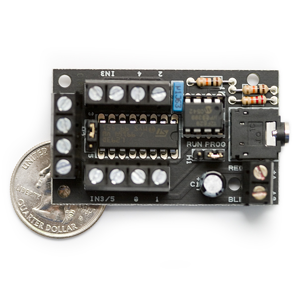
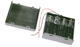
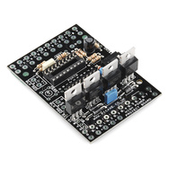
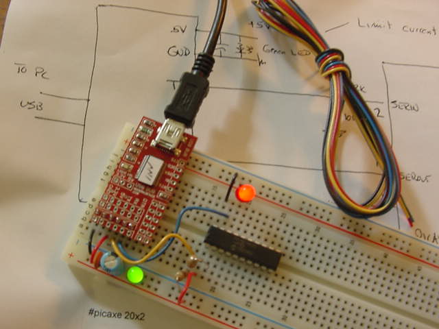
Build a Robot From A Power Wheelchair ... 32040 Views Author's name: WeRbots I bought a power wheelchair with the idea it was the best way to get cheap motors and a framework for a "big bot" that I could use to haul junk and do robot sorts of things. My wife kept telling everyone I had a Power Chair - So I hurried up and put the thing under picAxe control, so my wife would now say I was working on a Robot - From a Wheelchair. Now it is an official Robot. There is more to do. I want to make a set of sensors. And I want to make a remote control. I want it to be autonomous, but I want to tell it what to do, and let it figure out "how." Now I have the base unit under computer control, so all the rest is adding fun! Author's Assigned Keywords: picAxe 18x picAxe 18m2 Robot Motor Control Robot robot bending (ad) Exploratorium I had to dig around a bit to figure out enough of the wheelchair electronics to get things going. Basically, you have a joystick which moves voltages (analog) +- a given voltage range (couple of volts) so the green wire inside the controller box provides a center voltage reference as the whole thing is built around a 12 volt control system. Thus dead center = whatever`s on the green wire. It is tough to find information on the web, especially for this pretty old analog system. But it`s the old systems we circuit benders can afford. A new power chair retails as better than a couple or three thousand bucks, and go up from there. On the junk market, you can find wheelchairs for even less. And, yes, though you can save a bundle on the powerful motors that come with a power chair. But: there are other certain costs. Like Batteries. Prepare to hold your breath when you find out how much batteries will cost ya. If you can locate a power chair for less than $300, but you have a large bill for batteries waiting for you. Don`t forget there is a system cost, no matter how cheap you get the initial power chair. This promises to be one fun project! Get Into The Power Chair You have to "open-up" the controller in order to override the joystick and put the power chair under the command of your controller chip. In this case a picAxe 18 pin series, you can use either the 18x or the 18m2. No one would buy an 18x when you can get a more powerful 18m2 for the same or less. Remove the seat and the arm mounting mechanism on the control box (with the joystick). Remove the four screws, two long, two short in the joystick control box and you have access to the important parts. Connect Wires Carefully Don`t over heat things too much and use a pretty small soldering iron so you don`t "unwire" anything while you are tacking on the connection wires. The method we use for controlling requires only four wires (we don`t need the green wire for a center reference, we don`t care what the center is, we will pull up (forward on one wire right turn on the other) or pull down the voltage (backwards on one wire, left turn on the other). Thus by raising or lowering the voltage we can decide whether or not to go back/forward and left/right. We will accomplish this by using 1/2 an H bridge to either be open (enable low) or connected to plus when it`s a logic 1 or sucking current to ground (lowering the voltage) to do the opposite action. Now we can go forward and turn at the same time, meaning we can swerve around objects rather than having to stop-and turn as a separate operation. Now Modify the picAxe Power Project Board The power project board needs to be tweaked a bit before you can use it to drive the actual power chair. You can see I have removed three of the four power FET`s from the board, but you don`t have to do all that. Basically you are going to bend the pins on the H-Bridge chip. Pin 1 and Pin 9 are bent out from the chip and wires will connect them so you can enable and disable the chips. So you bend the pins of the H-bridge straight out, then put the chip in the socket. Wire the two protruding pins output 3 and output 2 to allow you to operate the enable pins on the H-Bridge so you can provide a 3-state output signal to parallel the existing joystick inside the controller box. Now you can output a positive voltage (greater than the reference point), you can put out a negative to reference voltage or you can put out a completely open circuit, by pulling the enable pins low and high disabling and enabling the chips control over the two signal wires that now come out of the control board. This is what gives you control over the power chair, while still leaving the power chair controls operational. That was one of my goals, to be able to convert the bot back into a power chair whenever. This means this robot conversion can be used to retrofit an existing power chair for robotic remote control. This is one of the best applications - allowing the user to use a standard remote transmitter/receiver setup (like for model planes) to drive pins on the 18m2 chip and allow the power chair user to remotely move the chair. That means you could ride your chair to the car, get in the driver`s seat of the car and store the power chair in another operation. You can also "call" the power chair to your side this way. This approach is why I used the existing simply programmed 18m2 and the $12 PC board in my design approach. I could actually make something useful for someone who is otherwise handicapped. You know. Make something for actual usefulness :-) Hardware Schematic and Starter Software Here is the actual schematic of the changes to make to the picAxe power board. And the listing of the "Hello World" for robots program: `----------------------------------------------------------------------------- `------------------------------------------------------------------------------ ` `------------------------------------------------------------------------------ ` COMPILER DIRECTIVES / SYMBOLS `------------------------------------------------------------------------------ ` ` ` ------------------------------------------------------------ ` Compiler Directives #picaxe 18m2 ` ------------------------------------------------------------ ` `-------------------------------------------------- ` PicAxe 18M2 ` ` Pinout and Definition of Legs `======================================= `(DAC / Touch / ADC / Out / In) C.2 leg 1 `(SRQ / Out) Serial Out / C.3 leg 2 `(In) / Serial In / C.4 leg 3 `(In) old reset is now signal C.5 leg 4 `--------------------------------------- `(gnd) 0v leg 5 `--------------------------------------- `(SRI / Out / In) B.0 leg 6 `(i2c sda / Touch / ADC / Out / In) B.1 leg 7 `(hserin / Touch / ADC / Out / In) B.2 leg 8 `(pwm / Touch / ADC / Out / In) B.3 leg 9 `======================================= `---- package bottom -- direction up ---------- `======================================= `(i2c scl / Touch / ADC / Out / In) B.4 leg 10 `(hserout / Touch / ADC / Out / In) B.5 leg 11 `(pwm / Touch / ADC / Out / In) B.6 leg 12 `(Touch / ADC / Out / In) B.7 leg 13 `--------------------------------------- `(vcc) +v leg 14 `--------------------------------------- `(Out / In) C.6 leg 15 `(Out / In) C.7 leg 16 `(Touch / ADC / Out / In) C.0 leg 17 `(Touch / ADC / Out / In) C.1 leg 18 ` `======================================= `-------------------------------------------------------------- `-------------------------------------------------------------- ` Actual Code starts Here `-------------------------------------------------------------- `-------------------------------------------------------------- ` ` set motor drivers to known position ` turn all motor enables OFF symbol in3 = b.7 symbol in4 = b.6 symbol en34 = b.2 symbol in1 = b.5 symbol in2 = b.4 symbol en12 = b.3 ` stop everything low en34,in4,in3,en12,in2,in1 pause 3000 main: gosub moveForward pause 1000 gosub stopFB pause 1000 gosub moveBackward pause 1500 gosub stopFB pause 2000 gosub turnRight pause 1000 gosub turnLeft pause 1500 gosub stopTurn goto main moveForward: high in3 low in4 high en34 pause 10 return moveBackward: high in4 low in3 high en34 pause 10 return stopFB: ` stop forward/backward motion low en34 `drive off pause 10 return turnRight: high in1 low in2 high en12 pause 10 return turnLeft: high in2 low in1 high en12 pause 10 return stopTurn: ` stop right/left motion low en12 `drive off pause 10 return What to look out for with YOUR setup. How to make friends with your particular power chair joystick. You make friends with the joystick and the controller, by determining the parameters where the wheelchair electronics tells you, you have hit a limit they are monitoring for in the chair safety system. I don`t want to muck about with that area too much, else I will have a robot, not a wheelchair modification, so learn to live with your chair`s rules. Assuming you know the wheelchair obeys it`s self on most days, you can measure the voltages on the thing while running in neutral or on blocks. The rig in the photo is simply a way to click on a pot 10k is what I used, to adjust, push button, and watch the controller and hear the engine roar. Why two switches? All good experiments start out well-intended, I wanted to adjust two controls, one for forward the other reverse. But, I cheated a bit and measured things (I have a voltmeter ;) so I already knew I needed to move plus or minus two volts with a center voltage of 5.8 volts... The little switches merely verified that two things could happen. One way I could use two resistors each with the proper values, or I could simply find a value that would work both ways. I could make up for the actual speed difference by using timing, just run the wheels for a longer time and they will get there at the same time as the faster wheels. 1/2 a second go forward 3/4 a second to move the same distance backwards. For my setup, that meant I needed to pull a 5.6K resistor to ground (and the center pin of the joystick) to pull the voltage lower. All I needed was a transistor to do that. And. By devious choice of the value 5.6K, going forward meant connecting to a nice high positive voltage larger than 5.8 volts. This time you move the 5.6K to the plus 12 volt power pole and voila! Fast forward please. By using an H-bridge, I became the lazy hacking circuit bender and used the picAxe power board to run the test vehicle for me. Now using one of the forward motor drive terminals gives me three states and makes me a good neighbor to the actual joystick to which we have attached ourselves. Like a good neighbor we jump from +7 to -0.6 (I see we are using silicon transistors here :) and better still sit quietly completely disconnected from the joystick the rest of the time. Thanks H-bridge, for the tri-state outputs! Now I can play around with helping chair user avoid smashing the walls at every door opening into what looks like spear heads after a joust. Coming Soon?? 1. R/C controller setup. Makes this a practical application for someone who is handicapped and can do a little soldering (or with a friend who can do some soldering). 1a. First steps to move this and Pong forward are to build a power supply using 12v (or more) which supplies 3.3v, 5v, 6v (servos),12v(pongs)... Maybe with a controlled bootup sequence? Maybe not :-) too much! 1b. Create a freq generator with sweep control (analog) to test coils tuned to 40kHz, add protection diodes. How simple is it? Very. Just hook pwm channels to a couple of spare input pins, decode the commands into commands appropriate to the wheelchair. 2. Autonomy. Add sensors so the thing becomes an autonomous robot. I want to tell it to come to me - then figure out it`s own plan to do it. Could use the rf transmitter along with it for signalling. Also could follow a string of lamp cord tied together at the distant end fed with an oscillator, a sensor on the bot could line it up with the buried cord which would allow it to follow various prescribed paths. Like a line follower without the line. Line following would be another way to do the above inside a building. 3. The usual, camera, remote controlled, stuff like that. 4. A follower that would align the power chair with an attendant for shepherding people through airports, hospitals and the like. And that`s the list for the time being. I`m sure I`ll think up a list of things. Watch for `em to show up here on C What I Can Do! It's Easy To: C - What - I - Can - Do • Sign up - Get ID and Password• Plan and Create a Project That Someone Might Enjoy and May Even Want to Build• Link to your creation on your favorite social networking site or blog.• Become famous! Because your projects get a lot of Hits!
|
By Creators DoctorZoidberg: Converting a Flashlight to LED DoctorZoidberg: Home Project: MUTE TV Wearable TV Muter! DoctorZoidberg: Scare Crow - For Modern Gardens - Home Project jim: CwhatIcanDo Website jim: Tour This Website PaulSandin: Butler, a low-cost mobile robot base WeRbots: BEAM BOT: HexBug Exposed! WeRbots: Buggy Bot: Wire Frame Bot Body WeRbots: Easy Cheap Robot Weekend Project WeRbots: RFL Robot Out Of The Box Experience WeRbots: Robot Man: With Robot Demos WeRbots: Build Your Own Track Drive Robot WeRbots: Build a Robot In 5 Minutes WeRbots: i-Mon App WeRbots: How To Make A Virtual Robot in FLASH WeRbots: Droid From Motorola :: A Robot ? WeRbots: Robots Almost Anyone Can Afford WeRbots: How To Build a Robot in a Box WeRbots: picAxe 18m2 for robotics WeRbots: Build a Respectable Autonomous Robot WeRbots: On Line Neighborhood Watch WeRbots: Pong))))) WeRbots: Roboteer`s Guide to BeagleBone Black WeRbots: Autonomous Robot PVC "Pickup Truck" |
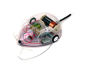
By Keywords Action Script 2: How To Make A Virtual Robot in FLASH Ajax: CwhatIcanDo Website Ajax: CwhatIcanDo Specs: RC2 Ajax: battle Android: Droid From Motorola :: A Robot ? Android: battle batting cage installation: Home Installation of a 4 Section In-Ground Batting Cage BEAM Robots: BEAM BOT: HexBug Exposed! BEAM Robots: picaxe 8m: Wall Follower Mouse gets Majorly Modded BEAM Robots: How to build simple analog balancing robots BEAM Robots: battle Block Watch Cam: On Line Neighborhood Watch Cheap Robot: Easy Cheap Robot Weekend Project Cheap Robot: How To Build a Robot in a Box Cheap Robot: Autonomous Robot Built From Power Chair Wheelchair commercial killer: Home Project: MUTE TV Wearable TV Muter! Convert Your Flashlight to LED: Converting a Flashlight to LED Create a Project: HELP :: How To Create a Project CwhatIcanDo HELP: HELP :: How To Create a Project Do it Yourself: Robots Almost Anyone Can Afford Do it Yourself: Scare Crow - For Modern Gardens - Home Project Do it Yourself: Wheelchair Works 3 Ways: Manual, R/C, and Autonomous Do it Yourself: On Line Neighborhood Watch Droid Smart Phone: Droid From Motorola :: A Robot ? Easy to Make Robot: Easy Cheap Robot Weekend Project entertainment: Home Project: MUTE TV Wearable TV Muter! FLASH Applications: How To Make A Virtual Robot in FLASH HELP: Tour This Website How To: CwhatIcanDo Website How To Build Cheap Bots: Robots Almost Anyone Can Afford How To Build Cheap Bots: How To Build a Robot in a Box How To Website: Tour This Website How To Website: CwhatIcanDo Website Infrared Proximity Sensor: Build Your Own Track Drive Robot IR Detector: Build Your Own Track Drive Robot Lighting Projects: Converting a Flashlight to LED logic analyzer: An affordable Logic Analyzer for the workbench. multi: Multi Media Messaging Device Mute the TV: Home Project: MUTE TV Wearable TV Muter! open source: An affordable Logic Analyzer for the workbench. picAxe: Build Your Own Track Drive Robot picAxe: picAxe 18m2 for robotics picAxe 08m: Robots Almost Anyone Can Afford picAxe 14m: picAxe 14m Motor Driver Board: Make Your Own picAxe 14m: How To Build a Robot in a Box picAxe 18m2: picAxe 18m2 for robotics picAxe 18m2: Weekend Project: Get Started With Robots picAxe 18m2: Build a Robot From A Power Wheelchair picAxe 18m2: Autonomous Robot Built From Power Chair Wheelchair picAxe 18m2: Wheelchair Works 3 Ways: Manual, R/C, and Autonomous picAxe 18x: How To Build a Robot in a Box picAxe 18x: picAxe 18m2 for robotics picAxe 18x: Build a Robot From A Power Wheelchair power wheelchair: Wheelchair Works 3 Ways: Manual, R/C, and Autonomous Quick Build Robot: Build a Robot In 5 Minutes RFL Robots: Building an RFL Inspired Upright Robot Base RFL Robots: RFL Robot Out Of The Box Experience robot bending: Morphibian Land Shark robot bending: Build a Robot From A Power Wheelchair Robot Man: Robot Man: With Robot Demos Robot Motor Control: Build the L298 H-Bridge Motor Control Robot Motor Control: Robot Basics Robot Motor Control: picAxe 14m Motor Driver Board: Make Your Own Robot Motor Control: Buggy Bot: Wire Frame Bot Body Robot Motor Control: picAxe 8 bit Motor Controller: Look Inside Robot Motor Control: How to build simple analog balancing robots Robot Motor Control: Build a Robot From A Power Wheelchair Robot Motor Control: Autonomous Robot Built From Power Chair Wheelchair Robot Pets: DogBot the Robo Dog : Robotic WatchDog Robot Pets: Operation of the Tri-Bot From Wowwee! Robot Pets: Robot Man: With Robot Demos robotics: Droid From Motorola :: A Robot ? robotics: Easy Cheap Robot Weekend Project Robots: BEAM BOT: HexBug Exposed! Robots: Robot Basics Robots: Buggy Bot: Wire Frame Bot Body Robots: Build a Robot In 5 Minutes Robots: Build Your Own Track Drive Robot Robots: Easy Cheap Robot Weekend Project Robots: How To Build a Robot in a Box Rumble Bot Conversions: Robots Almost Anyone Can Afford Security System: On Line Neighborhood Watch Select or type in a Keyword: Converting a Flashlight to LED track drive robot: Build Your Own Track Drive Robot Virtual Pet Robot: How To Make A Virtual Robot in FLASH web: CwhatIcanDo Website web 2.0 site: CwhatIcanDo Website web 2.0 site: CwhatIcanDo Specs: RC2 Weekend Project Robots: Easy Cheap Robot Weekend Project Weekend Project Robots: Weekend Project: Get Started With Robots |
Click To Expand / Contract Menus. View by Creator, Category, Keywords or Number of Views.